added 4 characters in body
Source Link

Most of us probably do not have 3DS Max and even fewer can do anything useful with it. I am not an exception. 3DS Max has numerous common geometry definition methods. Beyond them it even can simulate physics and make realistic material deformations (seen only demos) so an advanced 3DS Max user may well let a hammer hit a straight round tube to make its ends flat.

In case you are not interested in simulating hammering, but want an easy to make lookalike try for ex. this:

enter image description here

2 circles and a rounded rectangle are blended to get a surface. This is a common method to generate solid pieces and shells which have smoothly changing cross-section profiles. Here those profile samples are placed on a straight line, but generally programs allow also one to useinsert a curved sweep railsrail. The method is in some programs called lofting and it's blending or sweeping in others. One must also define does he want a filled solid or a surface. This example has a zero thickness surface.

Making realistic looking joints to other truss structure parts is another problem. It was not asked here.

Most of us probably do not have 3DS Max and even fewer can do anything useful with it. I am not an exception. 3DS Max has numerous common geometry definition methods. Beyond them it even can simulate physics and make realistic material deformations (seen only demos) so an advanced 3DS Max user may well let a hammer hit a straight round tube to make its ends flat.

In case you are not interested in simulating hammering, but want an easy to make lookalike try for ex. this:

enter image description here

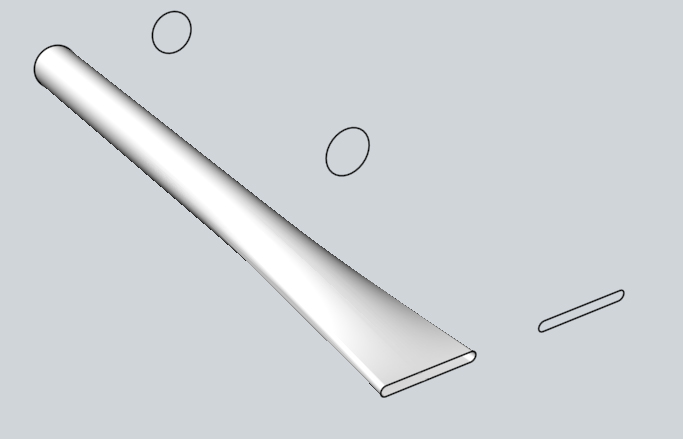
2 circles and a rounded rectangle are blended to get a surface. This is a common method to generate solid pieces and shells which have smoothly changing cross-section profiles. Here those profile samples are placed on a straight line, but generally programs allow also one to use curved sweep rails. The method is in some programs called lofting and it's blending or sweeping in others. One must also define does he want a filled solid or a surface. This example has a zero thickness surface.

Making realistic looking joints to other truss structure parts is another problem. It was not asked here.

Most of us probably do not have 3DS Max and even fewer can do anything useful with it. I am not an exception. 3DS Max has numerous common geometry definition methods. Beyond them it even can simulate physics and make realistic material deformations (seen only demos) so an advanced 3DS Max user may well let a hammer hit a straight round tube to make its ends flat.

In case you are not interested in simulating hammering, but want an easy to make lookalike try for ex. this:

enter image description here

2 circles and a rounded rectangle are blended to get a surface. This is a common method to generate solid pieces and shells which have smoothly changing cross-section profiles. Here those profile samples are placed on a straight line, but generally programs allow also one to insert a curved sweep rail. The method is in some programs called lofting and it's blending or sweeping in others. One must also define does he want a filled solid or a surface. This example has a zero thickness surface.

Making realistic looking joints to other truss structure parts is another problem. It was not asked here.

added 6 characters in body
Source Link

Most of us probably do not have 3DS Max and even fewer can do anything useful with it. I am not an exception. 3DS Max has numerous common geometry definition methods. Beyond them it even can simulate physics and make realistic material deformations (seen only demos) so an advanced 3DS Max user may well let a hammer hit a straight round tube to make its ends flat.

In case you are not interested in simulating hammering, but want an easy to make lookalike try for ex. this:

enter image description here

2 circles and a rounded rectangle are blended to get a surface. This is a common method to generate solid pieces and shells which have smoothly changing cross-section profiles. Here those profile samples are placed on a straight line, but generally programs allow also one to use curved sweep rails. The method is in some programs called lofting and it's blending or sweeping in others. One must also define does he want a filled solid or a surface. This example has a zero thickness surface.

Making realistic looking joints to other truss structure parts is another problem. It was not asked here.

Most of us probably do not have 3DS Max and even fewer can do anything useful with it. I am not an exception. 3DS Max has numerous common geometry definition methods. Beyond them it even can simulate physics and make realistic material deformations (seen only demos) so an advanced 3DS Max user may well let a hammer hit a straight tube to make its ends flat.

In case you are not interested in simulating hammering, but want an easy to make lookalike try for ex. this:

enter image description here

2 circles and a rounded rectangle are blended to get a surface. This is a common method to generate solid pieces and shells which have smoothly changing cross-section profiles. Here those profile samples are placed on a straight line, but generally programs allow also one to use curved sweep rails. The method is in some programs called lofting and it's blending or sweeping in others. One must also define does he want a filled solid or a surface. This example has a zero thickness surface.

Making realistic looking joints to other truss structure parts is another problem. It was not asked here.

Most of us probably do not have 3DS Max and even fewer can do anything useful with it. I am not an exception. 3DS Max has numerous common geometry definition methods. Beyond them it even can simulate physics and make realistic material deformations (seen only demos) so an advanced 3DS Max user may well let a hammer hit a straight round tube to make its ends flat.

In case you are not interested in simulating hammering, but want an easy to make lookalike try for ex. this:

enter image description here

2 circles and a rounded rectangle are blended to get a surface. This is a common method to generate solid pieces and shells which have smoothly changing cross-section profiles. Here those profile samples are placed on a straight line, but generally programs allow also one to use curved sweep rails. The method is in some programs called lofting and it's blending or sweeping in others. One must also define does he want a filled solid or a surface. This example has a zero thickness surface.

Making realistic looking joints to other truss structure parts is another problem. It was not asked here.

Source Link

Most of us probably do not have 3DS Max and even fewer can do anything useful with it. I am not an exception. 3DS Max has numerous common geometry definition methods. Beyond them it even can simulate physics and make realistic material deformations (seen only demos) so an advanced 3DS Max user may well let a hammer hit a straight tube to make its ends flat.

In case you are not interested in simulating hammering, but want an easy to make lookalike try for ex. this:

enter image description here

2 circles and a rounded rectangle are blended to get a surface. This is a common method to generate solid pieces and shells which have smoothly changing cross-section profiles. Here those profile samples are placed on a straight line, but generally programs allow also one to use curved sweep rails. The method is in some programs called lofting and it's blending or sweeping in others. One must also define does he want a filled solid or a surface. This example has a zero thickness surface.

Making realistic looking joints to other truss structure parts is another problem. It was not asked here.