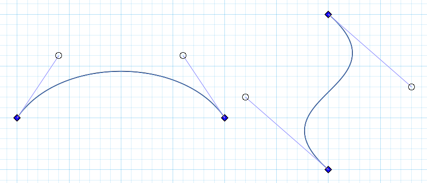
The older answer is fine, but the places of the nodes and handles are limited to the grid. That shouldn't be any harm if the grid is dense enough and one can accept between his ears the caused placement, size and direction quantization.
But lets assume the line between the endpoints of the curve is already given and there's no grid.

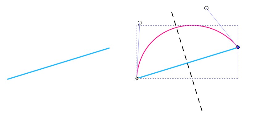
The starting point is the straight blue line in the left. The wanted curve (red) is inserted in the right. It must be symmetric, the mid-normal of the blue line line (dashed black) should be the symmetry axis. One should be able to adjust the red curve without deleting the symmetry as long as he wants and without being restricted by a grid.
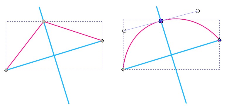
One possibility is to insert the mid-normal and use it as a guide for the midpoint of the curve. It works if all snap to points are ON:

In the left the mid-normal is created by duplicating the blue line and by clicking "rotate 90 degrees" in the info panel. A symmetric path (red) which contains only straight segments is created by clicking with the Bezier tool three times and by pressing Enter.
In the right the midpoint node is selected with the node tool and turned to symmetric.
You can move the midpoint node freely along the mid-normal and you can stretch the handles. Hold the Ctrl-key to keep the original handle direction. Beware: It snaps easily also to other directions, but the original direction is one of the possible snaps. Of course, you can insert a copy of the original blue line to the midpoint node and use it as a solid snapping guide for the handles.
When the curve is good you can remove the extras. If you want it as 2-nodes-only, you can simply delete the midpoint node. The curve stays, but the endpoint handles appear like in my 1st image. Warning: The midpoint node must be symmetric. Otherwise the symmetry vanishes when the midpoint node is deleted.


