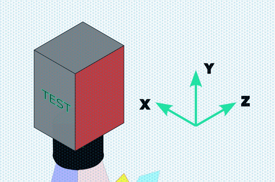
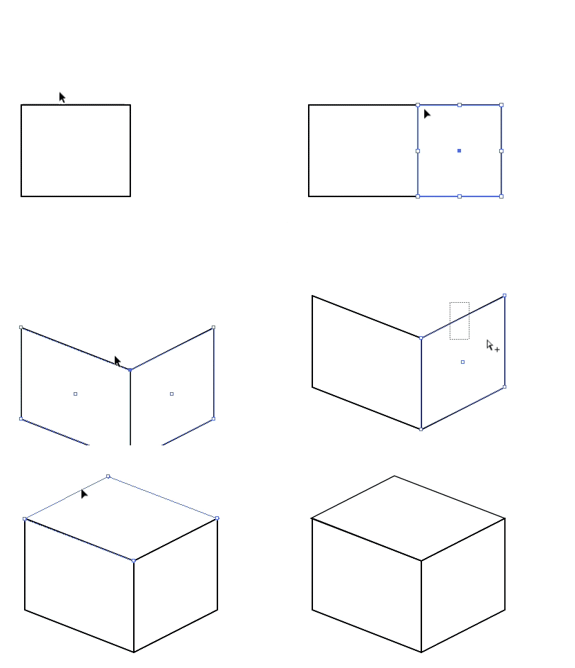
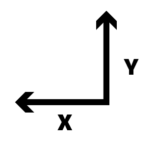
There's no easy way to transform the already drawn box to the new rotation. It's possible if one knows and understands 3D projection math and how it can be used in Inkscape. Without that knowledge you do better by drawing a new box. I'll follow the latter route.
I counted the grid divisions of your "TEST" box, assumed that 1 div = 1 millimeter and drew 2 flat straight on the face rectangles of the same box.
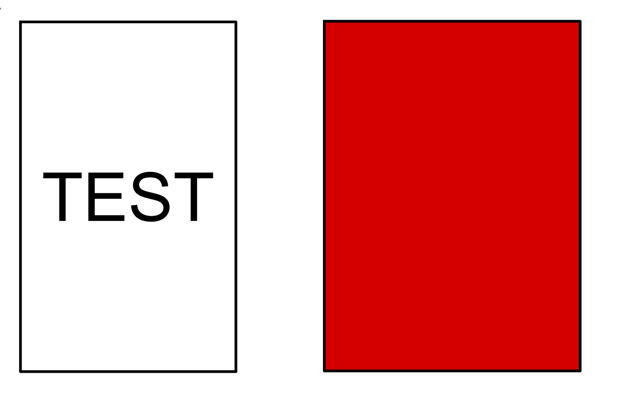
Both are 26 millimeters tall. The red one is 19 millimeters wide and the other is 16 millimeters wide. There's no need to draw the 3rd (=top) face, it comes automatically right because this is a rectangular box.
We construct from these a copy of your original isometric box and a rotated version of it. The rotation is wanted around an axis which is parallel with the z axis. The angle is still undefined, but I guess it can be 30 degrees. The method is usable as well with other rotation angles, but the rotation axis must be parallel with one of the edges of the original box.
If the rotation axis was arbitary I wouldn't try to do the same in Inkscape, it would be much easier to use a 3D program (see NOTE1) - no matter the construction has been known hundreds of years as a part of engineering.
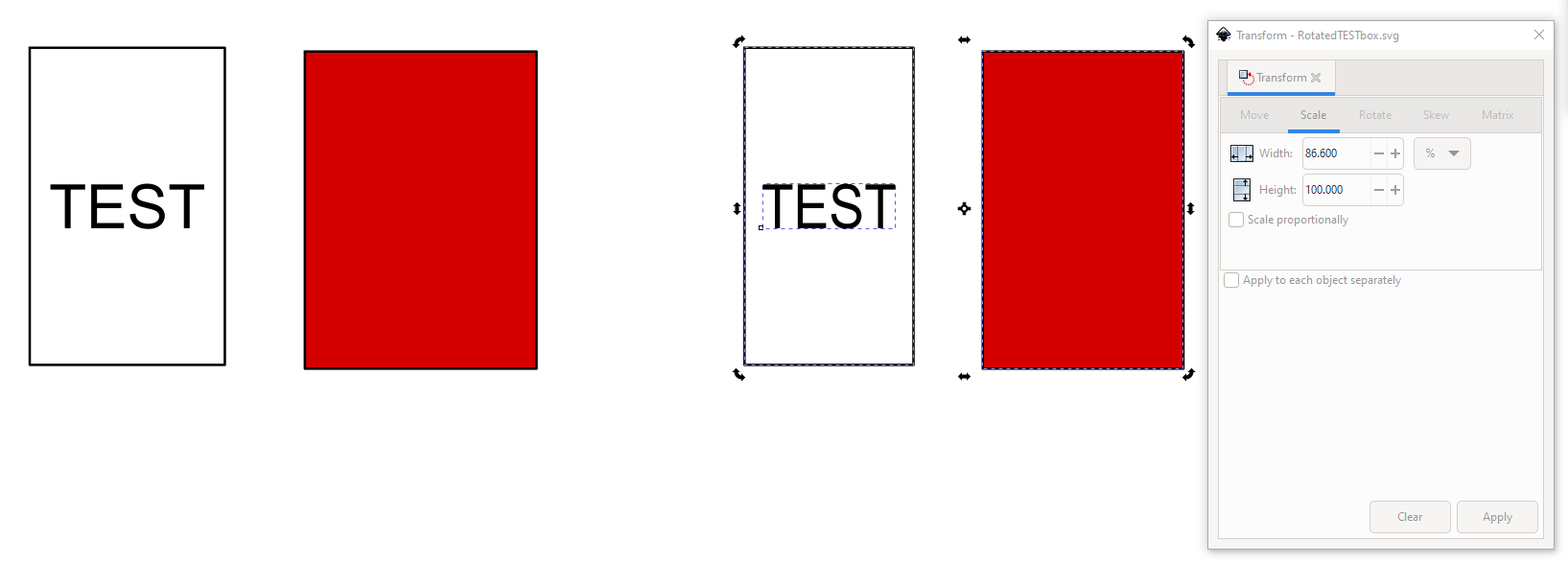
To convert the reconstructed flat faces to your original isometric projection is simple. One can use Inkscape's dialog Object > Transform. From there one needs tabs Scale and Skew. At first one must scale the items horizontally to 86,6%. The number is an approximation of sqrt(3/4), but it is good enough for this problem.
The original flat versions and their scaled copies are in the next image:
Then there's the skewing. The left one must be skewed vertically +30 degrees and the right one -30 degrees. We can just now cheat and skew both +30 degrees and flip horizontally the red face. In the next image they are skewed both +30 degrees and a flipped copy is made:
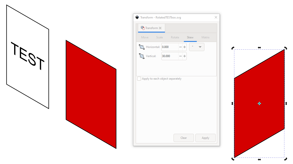
The parts snap together if you have all point snaps ON, but no snap to grid. The missing lines can be got by drawing with the Bezier tool (="the pen") on the top edges of the ready faces and moving the lines. They snap.
The manually drawn and moved lines are shown as blue in the next image. The rightmost version has colored faces. The top face cannot be colored as is, because it's not a closed shape. I drew a new 4-gon by clicking with the pen the corners.
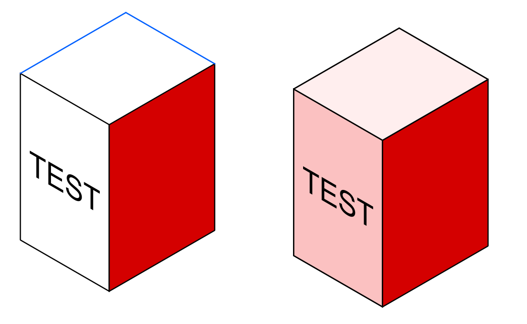
If it happens that the text must be lifted to top after coloring the face, you select it easiest in the objects panel.
Your rotation goal keeps the "TEST" face still parallel with the XY-plane, so the isometric view of the rotated version can be constructed exactly with the same scaling and skew than above, only rotate it at first.
The next image contains the needed versions:

In the left there's the reconstructed flat original. The rest are
- rotated 30 degrees (the angle can be arbitary)
- scaled horizontally to 86,6%
- skewed 30 degrees (for the isometric projection, no connection to the 30 degrees of the rotation)
- drawn with the pen the missing lines. The Z edge is copied from the non-rotated box. The 2 other edges are drawn on the skewed face edges and moved. They snap exactly.
The rotated red face would need totally different transformation, so it's constructed indirectly. I skip more general proceedings. In the next image the faces are redrawn with the pen as closed shapes and colored to white and red:
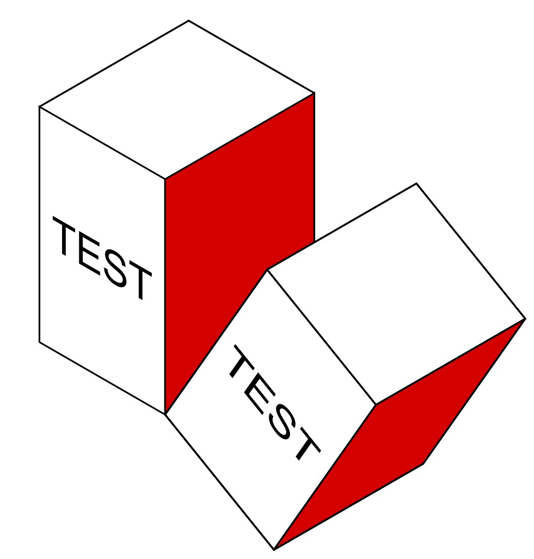
ADD: I didn't use the grid, because it's perfect only for parts which have the edges parallel with x, y and z axles. Nothing prevents to construct a new grid for certain rotation if one knows the projection math. I skip it.
The corners of the rotated version will fit only in some lucky cases to the original grid - like just in your case the z-edge could be recycled and that made the construction simple.
NOTE1: The next image is a screenshot from a simple 3d CAD program.
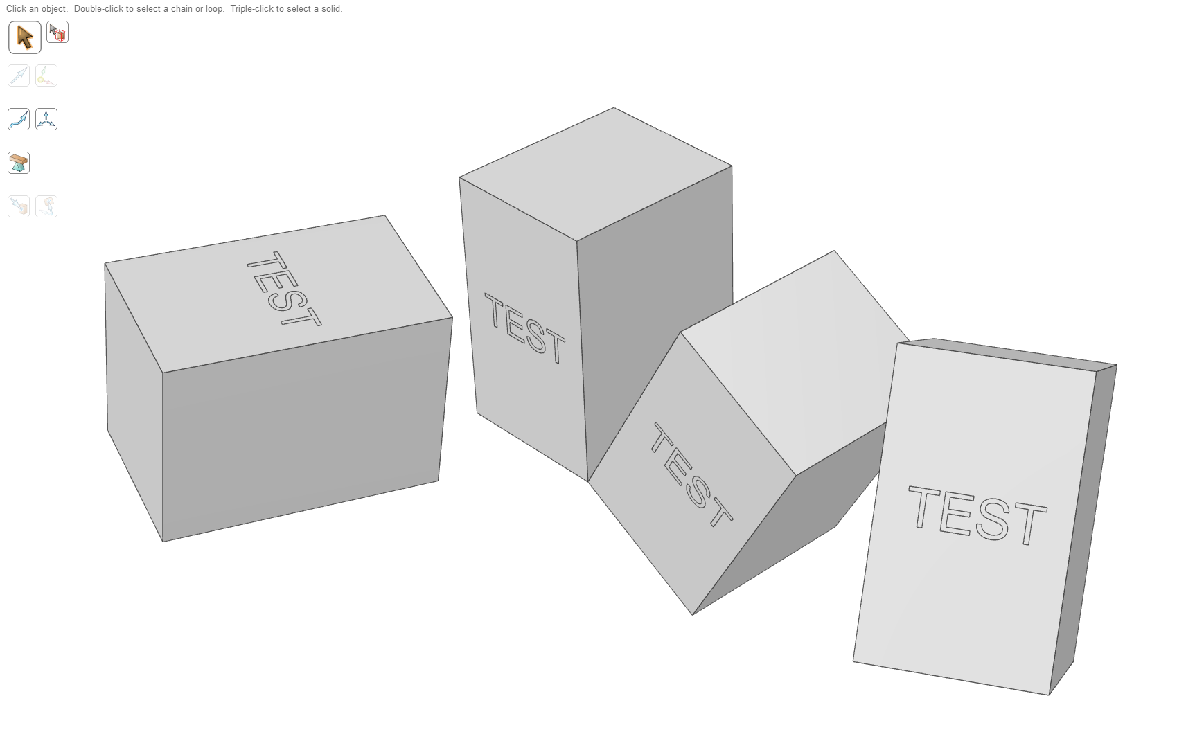
Drawing one box with certain dimensions and text is about as complex as making your original box in the grid. But all rotated copies took only a few seconds each. BTW. I switched the projection from isometric to a perspective projection, because for some reason the rotated boxes started soon to look distorted in isometric projection. There's no imaging error, it's a property of human vision.

