1

enter image description here

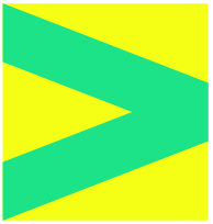
I would like to have a green shape like the first example.

  • the green shape should have a fixed height (height of letter d/g together)
  • yellow block is the shape where it should be in: so the green shape starts left-top in yellow shape and then goes to the middle (need it pixel perfect) of the right side of the yellow shape
  • when that is realised it's easy to duplicate the shape that goes that to the left again.

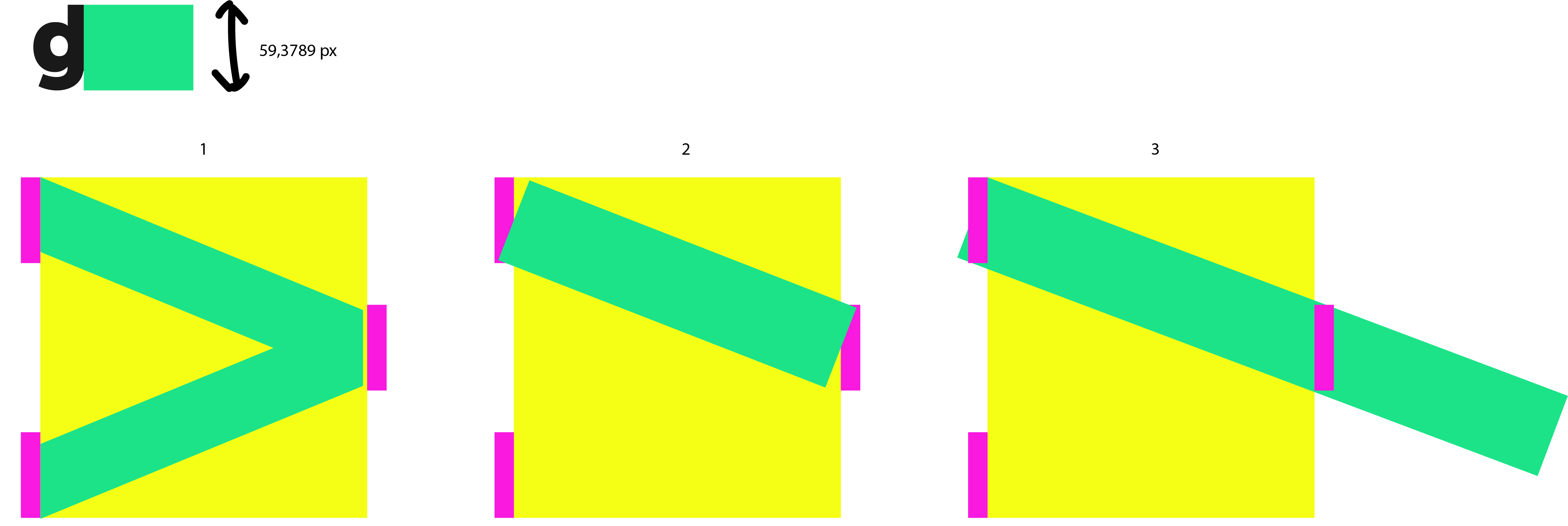
Second example I tried it first like this (pink shape same height a greenshape I want): make a path on the vertical centered point of the first pink shape and make another path pointer to the right middle pink shape (vertical centered). Than I give the path a line-thickness of 59,3...px. I should then extend still the line and than cut the parts of that goes out of the yellow shape. But: the line doesn't start then nice on the lefttop pixel. Not pixelperfect..

Third example Here I make the shape at the b/g very width and then I use the free transform and place the shape in the lefttop. Then I rotate the shape that it's stays fixed at the left top. That works but than it's not easy to make it pixelperfect in the middle of yellow right side block (or pinkmiddle right).

What is the best way to make the green shape in the line-thickness I want pixelperfect in the yellowbox?

1 Answer 1

6

If you want the vertical cut of the line to have a certain height

This is very easy to do with skewed rectangles.

  • Move the two magenta rectangles in the left side so they snap to the inside of the yellow rectangle.
  • Change their color to the wanted green.
  • In the upper green rectangle, select the two anchor points in the right side with Direct Selection Tool.
  • Place the mouse over the upper right anchor point and drag until that anchor point snaps to the upper left corner of the magenta rectangle.
  • Do the same with the lower green rectangle.
  • Delete the magenta rectangle.

If you want the line to have a certain width

This is way more complicated. We need to do some geometrical trickery.

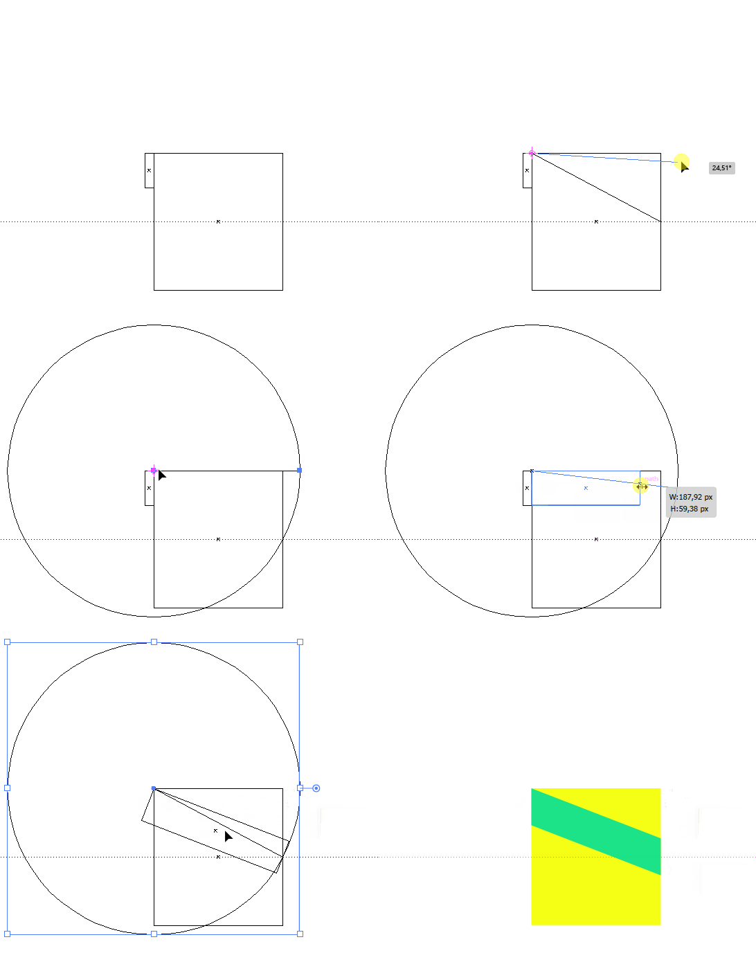
  • On the large rectangle, draw a line from the upper left corner to the middle of the right side.
  • Use Rotate Tool to rotate the line around the upper left corner. Grab the anchor point in the right side and rotate until the line is horizontal.
  • Draw a circle centered in the upper left corner with a radius as long as the line we just drew. This can be achieved by holding Shift and Alt while dragging.
  • Use Rotate Tool to rotate the line around the upper left corner. Grab the anchor point in the right side and rotate until that point snaps to the intersection between the vertical middle of the small rectangle and the path of the circle.
  • Drag the small rectangle wider until it snaps with that intersection we just found.
  • Select the small rectangle and the line and use Rotate Tool to rotate the selection around the upper left corner. Grab the anchor point in the right side of the line and rotate until that point snaps to the middle of the right side of the large rectangle.
  • Delete the line and the circle.
  • Extend the small rectangle a little bit on the right side.
  • Select the large rectangle and copy it to clipboard.
  • Select the small and the large rectangle and use Intersect in the Pathfinder panel.
  • Paste the large rectangle in the back.

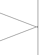
Now you can reflect the shape to get the final figure:

Unfortunately it seems that no matter how precisely you do all these operations the result will have some tiny inaccuracy. I believe it's caused by rounding errors when rotating and the fact that circles in Illustrator aren't perfectly round.

Here is one of the intersections in the right side at 64000%. I managed to make it fit with 0.0062 px accuracy.

I think I would just live with that. Or make the points on the right side of the green lines snap and then simply scale the two green lines to fit the yellow rectangle.

11
  • You're welcome! @user287001 encouraged me to post this and then deleted their own answer.
    – Wolff
    Commented Nov 15, 2020 at 10:28
  • Thank you for you great explanation. Still have a question about it. When I do this like this and I rotate a green block in the line of the new diagonal line there is a difference in height. I already tried it like this I think a week ago. ITs not such a big problem but I prefer to have the line-height as close as possible as the d/g height. See: ibb.co/QDNhdKN Only way to make the greenblock a little bit higher so that the diagonal line is also a little bit higher?
    – TonyHibbo
    Commented Nov 15, 2020 at 10:41
  • Then I misunderstood you! I thought that you wanted the vertical cut through the line to be 59,3789 px. Your 3rd drawing indicates that.
    – Wolff
    Commented Nov 15, 2020 at 10:45
  • Maybe I didn't explain completely right. I want that the diagonal line has the same height (indeed 59,3789px) as the purple blocks. But that is not the case now, it's a little bit smaller.
    – TonyHibbo
    Commented Nov 15, 2020 at 10:47
  • 1
    @Wolff it cannot be simplified, It can be made look shorter by calculating the needed rotation angle from the width of the square and the height of the green rectangle. Or by having a CAD plugin "draw tangent from a given point to a given circle"
    – user82991
    Commented Nov 15, 2020 at 17:54

Your Answer

By clicking “Post Your Answer”, you agree to our terms of service and acknowledge you have read our privacy policy.

Not the answer you're looking for? Browse other questions tagged or ask your own question.